If you’ve ever wondered whether your patent drawing meets the strict legal requirements or feared that a minor oversight could derail your patent application, you’re not alone. Clear, compliant patent diagrams or illustrations play a decisive role in how quickly an examiner can understand—and approve—your invention, so getting them right from the start can save you time, money, and frustration.
Key Takeaways
- Effective patent drawings prioritize technical clarity and legal acceptability over visual embellishment.
- Accurate line weights, consistent labeling, and smartly selected views contribute directly to stronger IP claims.
- Following standards reduces the chance of drawing rejections in patent applications and boosts how well your invention is understood.
Fundamental Principles Of Patent Drawing
Patent drawings do more than complement your written description—they’re a legal requirement whenever visualization is essential to claim clarity. If you skip or botch a detail, the U.S. Patent and Trademark Office (USPTO) might punt your application back, costing you extra fees and delays. Start with these fundamental rules so you can minimize risk and focus on illustrating innovation.
Main Patent Drawing Requirements
You must use strong, white, smooth, non-glossy paper (either U.S. letter—8.5 × 11 inches—or A4—21.0 × 29.7 cm) that’s free from creases, folds, or marks. Sheets can’t have any holes (no punching!), and every sheet must meet these margin specifications:
- Top: ≥ 1 inch (2.5 cm)
- Left: ≥ 1 inch (2.5 cm)
- Right: ≥ 5⁄8 inch (1.5 cm)
- Bottom: ≥ 3⁄8 inch (1.0 cm)
Use Uniform, High-Contrast Lines
Every line, number, and letter must be black, well-defined, and uniformly thick so it reproduces cleanly when scaled to two-thirds size. Primary outlines (visible edges) typically use 0.4–0.6 mm lines. Medium lines (around 0.3 mm) go for dimension and extension lines, while 0.2 mm lines serve for hatching, hidden edges, and centerlines. If your lines are too light or break when you zoom in, examiners will flag them for lacking “adequate reproduction characteristics.”
Limit Text; Prioritize Readability
Include only essential text. When you do label parts or sections, each character height must be ≥ 1⁄8 inch (3.2 mm). Use a simple, legible font—sans-serif works best. All text must run horizontally, even if the feature is vertical on the page, so you never force the reviewer to rotate their head or their monitor.
Reference Characters: Consistency Matters
Each reference numeral (or letter, though numerals are preferred) must match exactly between the drawing and the written specification. Place numbers outside the feature, with a thin “leader line” (a short, straight line leading from the number to the element). Never enclose reference numerals in parentheses or brackets, and always orient them the same way as the view to avoid confusion.
Other Important Drawing Elements
- Shading (spaced, thin parallel lines) can clarify three-dimensional contours—like rounded surfaces or tapered edges—but use it sparingly so it doesn’t obscure reference numerals.
- Hatching is for section views. Draw hatching with regularly spaced, 45° oblique lines; if two adjacent parts share a common section, alternate hatching directions so they remain distinguishable. Break the hatching pattern whenever a reference numeral crosses it so the number remains legible.
Numbering Views and Sheets
Number each sheet consecutively as “1/3,” “2/3,” etc. (if you have three drawing sheets). Center that number at the top of the usable area (below the top margin). Each figure on a sheet gets an Arabic numeral (Fig. 1, Fig. 2, and so on). If a figure spans multiple sheets, maintain the same figure number but append letters (Fig. 2A, Fig. 2B). Don’t connect separate figures with projection lines—that’s strictly for sectional views.
Views to Include
- Orthographic Views: At a minimum, provide front, side, top, and bottom if they show unique features.
- Isometric or Perspective Views: Use these to communicate spatial relationships that two-dimensional orthographic views might miss (especially helpful for mechanical linkages or assemblies).
- Exploded Views: When parts fit together in a complex fashion, exploded views show relative positions clearly—label each sub-assembly with dashed lines pointing to its mating location.
Remember that provisional applications may accept looser sketches, but as soon as you file a non-provisional, all drawings must be USPTO-compliant. Submitting rough sketches in your priority document can actually cause more rework later, so aim for compliance from the outset.
Composition And Layout Standards
Even when you’ve mastered the basic requirements, how you organize views on a sheet significantly impacts readability. A well-laid-out page guides the examiner’s eye in logical order—saving them (and you) from avoidable questions and helping streamline the process of seeking a patent.
Group and Arrange Views Thoughtfully
- Place all views for a single figure together with minimal white space between them—avoid wasting sight space.
- Keep views straight; never rotate an entire figure unless it’s absolutely necessary for readability.
- If one view doesn’t fit, carry it cleanly to the next sheet but label them consistently so the examiner can reassemble mentally.
Maintain Proportion Without Noting Scale
USPTO prohibits explicit scale ratios (e.g., “Scale 1:2”) because reproduction may change sizes. Instead, draw each view large enough so that when it’s reduced to two-thirds scale, no detail is lost. If a tiny internal gear tooth pattern matters, present it as a separate “Detail A” (a close-up view), then draw an arrow from Detail A to the location on the main Fig. 1.
Avoid Excess Annotations
Every extension line, dimension arrowhead, and leader line adds visual clutter. Rather than over-annotate, consider a simple table of reference numerals and part names if space is tight, with a lone leader line pointing to the entire subassembly. Always double-check that no arrows point to the wrong edges and that every dimension line terminates at an extension line—not on the object itself.
Technical Execution And Standards
When you move from theory to execution, your ability to translate sketches into polished, USPTO-ready art hinges on consistent dimensioning, precise symbolism, and logical proportions. Inaccuracies here are the most common reasons for “drawing objections” in office actions.
Dimensioning And Annotation Practices
Never mix metric and imperial. Choose one (based on the specifications or your client’s preferences) and use it throughout. If you start in millimeters, keep everything in millimeters—including any callouts for tolerances.
When drawing dimension lines:
- Use thin (≈ 0.2–0.3 mm) dimension lines terminated with solid, filled arrowheads.
- Arrows must point to extension lines, never directly to the object; this way, the arrowheads don’t obscure fine features.
- Place dimensions outside the drawing when possible; if space is tight, use “breakout” close-up views or supplementary tables for small, dense parts.
When adding leader lines and reference numerals:
- Keep leader lines straight or gently curved; avoid zigzagging them around other features.
- Label numbers horizontally and at least 1⁄8 inch high for legibility.
- If a reference number sits on a cross-hatched section, interrupt the hatching to create a clear “window” for the numeral.
- A leader line may be replaced by underlining the numeral when space is extremely limited, but use this technique only sparingly to avoid confusion.
Drawing Conventions And Symbolism
Different line weights serve different functions:
- Solid Thick Lines (0.4–0.6 mm): Visible edges and outlines.
- Medium Lines (≈ 0.3 mm): Dimension, extension, and section-indicator lines.
- Thin Lines (≈ 0.2 mm): Hatching, hidden edges, and centerlines.
- Dashed Lines: Hidden edges (even spacing).
- Centerlines: Alternating long and short dashes (long dash at intersection).
Follow the graphical drawing symbols recognized by USPTO and ISO standards—for instance, use the conventional resistor or capacitor symbol for electrical schematics. For material hatching (steel, plastic, etc.), adhere to the sample patterns in 37 CFR 1.84. Deviating from these patterns can cause misinterpretation (e.g., two adjacent parts both hatched at 45° could appear as one solid piece).
Scale And Proportion Considerations
Your drawings do not need a scale legend (e.g., “Scale 1:10”) because the USPTO reduces everything to two-thirds size upon publication. Instead:
- Ensure that if a feature is critical (e.g., a micro-gear tooth), you provide a “Detail A” close-up.
- Label “Detail A” with a leader line pointing from the detail back to its original location in Fig. 1.
- Do not force disproportionate enlargements that distort relationships—examiners must trust your intent.
Overall assemblies should flow from macro to micro: start with an isometric “overview,” then offer orthographic or sectional views for internal mechanisms.
Number views sequentially:
- Overall assembly = Fig. 1
- Sectional view = Fig. 2
- Detail view = Fig. 2A
- Exploded view = Fig. 3
Professional Workflow And Quality Control
Drawing compliance isn’t a one-and-done affair; it’s a repeatable process that directly supports the overall process of seeking a patent. By breaking your workflow into discrete steps and instituting robust quality checks, you can file confident, examiner-ready illustrations on the first try.
Drawing Production Methodology
1. Discovery & Planning
- Read the specification thoroughly and identify every element that requires visual representation.
- Meet (in person, by call, or via email) with the inventor or patent attorney to clarify any ambiguous features.
- Sketch rough concepts on paper, labeling parts with placeholder numerals (e.g., “A,” “B,” “1,” “2”).
2. Initial Draft (Digital or Hand)
- If you’re hand-drawing, use India ink on suitable paper. If you’re digital, establish your preferred tool (AutoCAD, Adobe Illustrator, or a specialized patent-drawing software).
- Draft each figure with correct paper size/orientation, margin boundaries, and basic line weights.
3. Intermediate Review
- Insert dimension lines, leader lines, reference numerals, hatching, and shading (as needed).
- Check that no text or numerals sit outside the margins or within hatched areas.
4. Peer Review / Attorney Check
- Have another qualified illustrator or the patent attorney review each drawing against the checklist below. A second set of eyes helps catch details that could trigger drawing rejections in patent applications.
- Allow time for feedback—even minor feedback at this stage avoids last-minute surprises.
5. Final Revision & Refinement
- Implement feedback, tighten line weights, adjust hatching spacing, and confirm consistency across all figures.
- Test-print at actual size and two-thirds size to check for lost details or illegible text.
6. Final Approval & Export
- Verify final art files meet USPTO specs (PDF/A format is often required).
- Name files per convention (e.g., “ApplicantName_Invention_Fig1.pdf”) and confirm that metadata (e.g., sheet numbers) appear only within the “sight” area, not in the margins.
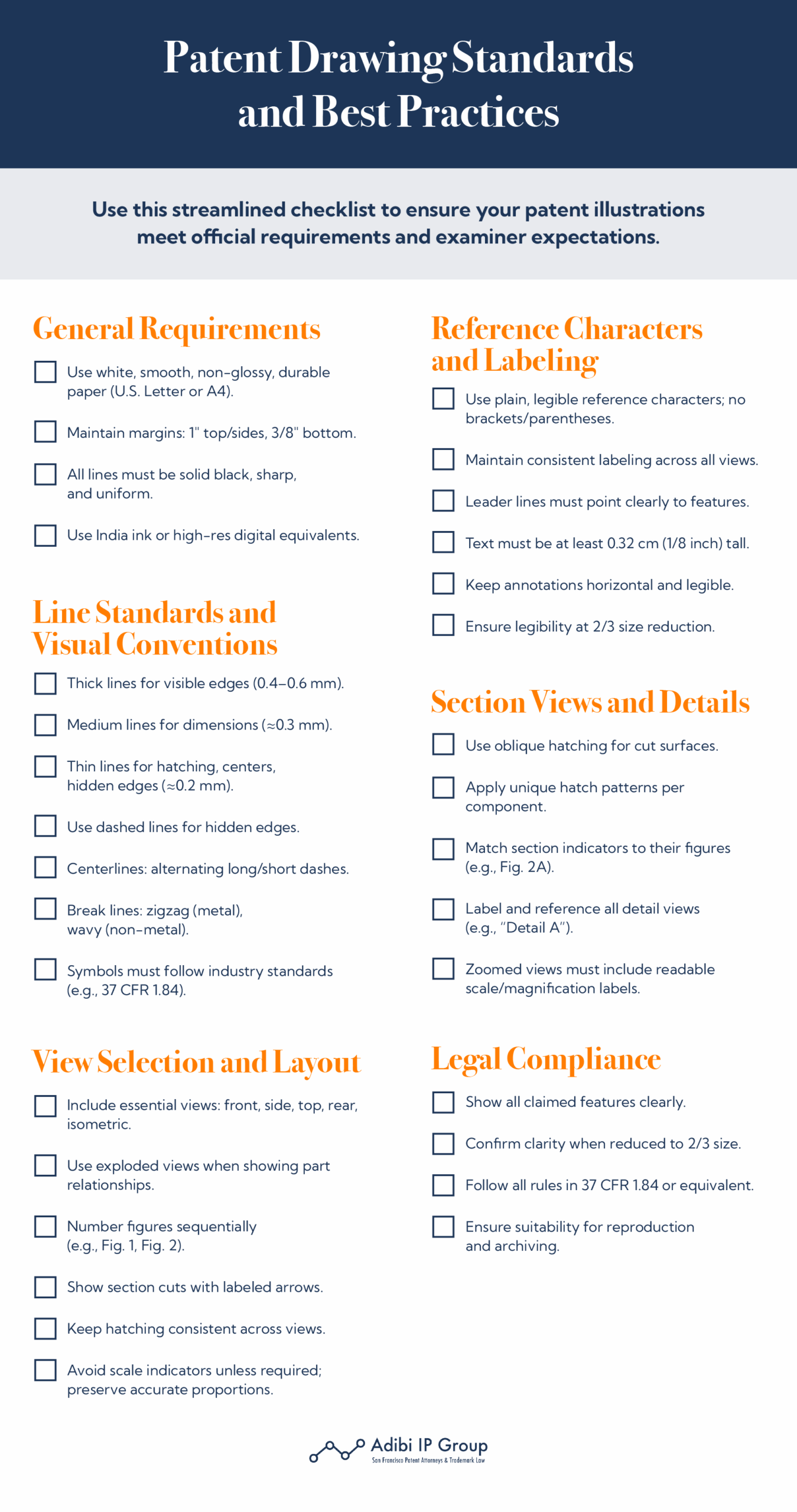
Quality Assurance Checklist
Below is a sample checklist modeled on 37 CFR 1.84. Adapt it to your project:
- Paper size: A4 or 8.5 × 11 inches, single side only.
- Margins: Top ≥ 2.5 cm; Left ≥ 2.5 cm; Right ≥ 1.5 cm; Bottom ≥ 1 cm.
- Sheet numbering: consecutive Arabic numerals (1 of N, 2 of N, …).
- View numbering: consecutive “FIG.” labels, correct order.
- Line weights: primary edges (0.4–0.6 mm); dimension lines (≈ 0.3 mm); hatching (≈ 0.2 mm).
- Reference numerals: plain, horizontal orientation, ≥ 3.2 mm height, outside features.
- Hatching: 45° oblique, consistent for each material, non-obstructing numerals.
- Shading: spaced lines, not solid blocks, if needed to show curvature.
- Text: horizontal orientation, ≥ 3.2 mm height, legible sans-serif font.
- No holes, no extraneous markings, no colored lines (unless absolutely required with justification).
- Figures aligned upright, no rotated views unless noted (“landscape mode”).
- Proportion: detailed views provided for small features.
Double-Check Your Patent Drawing Practices with Adibi IP Group
Your patent drawings are more than just illustrations—they’re legal documents that can make or break your application’s success. When you align your drawings with every requirement covered above—paper, margins, lines, hatching, views, and workflow—you transform uncertainty into confidence.
If you want expert partnership that blends legal insight with technical finesse, let Adibi IP Group help you ensure every line, numeral, and hatch stands up to scrutiny. We know that drawing rejections in patent applications can delay your success; let us help you avoid them. Discover how our team empowers innovators with bulletproof illustrations designed to expedite grant and protect your intellectual property. We can guide you through each step of the process of seeking a patent and safeguard your innovation at every turn.