Drawing-related flaws derail more patent applications than virtually any other issue. By tightening your patent diagram drawing process, you’ll cut needless delays, slash amendment costs, and sharpen your protection from day one. In this guide, you’ll walk through the leading rejection triggers, learn examiner expectations straight from the MPEP, and adopt preventive checklists—so your next patent diagram sails through without a hitch.
Key Takeaways
- Drawing inconsistencies and incorrect shading drive the majority of patent diagram rejections.
- Involving a skilled patent illustrator early helps mitigate common drawing rejection risks.
- Diligent prep and ongoing quality checks reduce costly corrections after submission.
Navigating The Complexities Of Patent Drawing Rejections
Patent drawing rejections can arise in design, utility, and plant applications whenever illustrations fail to meet the applicable rules under 35 U.S.C. 113, 37 C.F.R. 1.84, and the corresponding MPEP provisions. The following overview distills the core requirements and highlights common pitfalls across all patent types.
Illustrations are required “where necessary for the understanding of the subject matter sought to be patented,” and the USPTO may issue a notice under 35 U.S.C. 113 if drawings are inadequate or missing.
All patent drawings must be in durable, dense black lines on a white background, with uniform line weights and clear reproduction characteristics per 37 C.F.R. 1.84.
Margin and paper standards are strictly enforced—sheets must measure 21.6 × 27.9 cm (8½ × 11 in) or A4, with at least 2.5 cm top/left and 1.5 cm right margins; failure to comply triggers formal objections.
Reference numerals in utility and plant drawings must match the specification and be placed consistently outside the drawing boundaries to avoid confusion and subject-matter objections.
Crucial Issues to Assess During Rejection Reviews
- Missing or unclear reference characters: A top-10 list of utility drawing objections cites inconsistent numerals as a frequent cause of Formality Rejections under MPEP 714.
- Poor line quality or resolution: Faint, broken, or overly thick lines lead to reproducibility issues flagged under 37 C.F.R. 1.84 and MPEP 608.02.
- Incomplete views or angles: Plant patent applications require multiple angles and, if color is necessary, a petition under 37 C.F.R. 1.84(l); missing required views attracts formal objections.
- Inconsistent scaling and sectional details: Utility sectional views must include clear section lines and indicators per MPEP 608.01(f); mismatched scales can raise 35 U.S.C. 112 enablement concerns.
When addressing a rejection:
- Review the examiner’s remarks in light of the specific regulation or MPEP section cited.
- Compare against authoritative examples in the USPTO’s guidelines or published MPEP figures.
- Prepare annotated amendments showing how each correction addresses the rejection without introducing new matter.
Drawing Standards for Design Patents
A design patent application lives and dies on its drawings. A single mis-shaded surface or uneven line can open the door to a Section 112 rejection, leaving you scrambling to demonstrate enablement and written-description support.
Accuracy And Clarity
You must match every detail of the claimed design exactly. That means no guesswork: annotate texture lines, exclude hidden elements with broken lines, and keep proportions precise. If your spec contradicts the drawings, examiners flag inconsistency, undermining your entire claim.
Line Quality And Thickness
Uniform lines signal polish. Follow the USPTO’s drafting guidelines:
- Outer edges: 0.4–0.6 mm bold lines for clarity
- Detail lines: 0.25–0.35 mm mid-weight for internal features
- Fine textures: 0.15–0.20 mm for subtle shading cues.
Deviate and you risk objections for non-reproducibility or visual ambiguity.
Drawing Standards for Plant Patents
Plant patent drawings have their own nuances, codified in 37 C.F.R. 1.84:
- Color drawings: Generally not permitted except when color is necessary to disclose the claim; must be petitioned and paid for in advance.
- Photographs vs. line drawings: High-quality, black-and-white photographs are acceptable only when line drawings cannot show the invention adequately.
- Perspective and detail: Photographs must include multiple angles (typically front, rear, side, and close-up of distinguishing features) with consistent lighting.
- Labeling rules: Latin names of the plant variety must appear, and any reference keys must match the specification.
- Common drawing rejections: Unclear photographs, inconsistent lighting, lack of scale bars, and absence of required angles can all lead to formal objections.
Drawing Standards for Utility Patents
Utility patent drawings must convey every feature of the claimed invention clearly and completely. Under 35 U.S.C. 113 and MPEP Chapter 600.
- Scope of drawings: All elements recited in the claims must appear in the drawings, unless they are purely functional and can be described in the specification.
- Format requirements: Black-and-white line drawings on white paper (or equivalent digital rendering), 300 dpi minimum, with margins of at least 2.5 cm on each side.
- Numbering and labeling: Each drawing sheet must carry a sheet number and total sheet count; reference numerals must match those in the specification.
- Detail and scale: Scales should be uniform across multiple views, and sectional views must include section lines and indicators per MPEP 608.01.
- Common rejections: Missing reference characters, inconsistent numerals, blurry reproduction, and incomplete perspective or sectional views can all trigger Formality Rejections under MPEP 714.
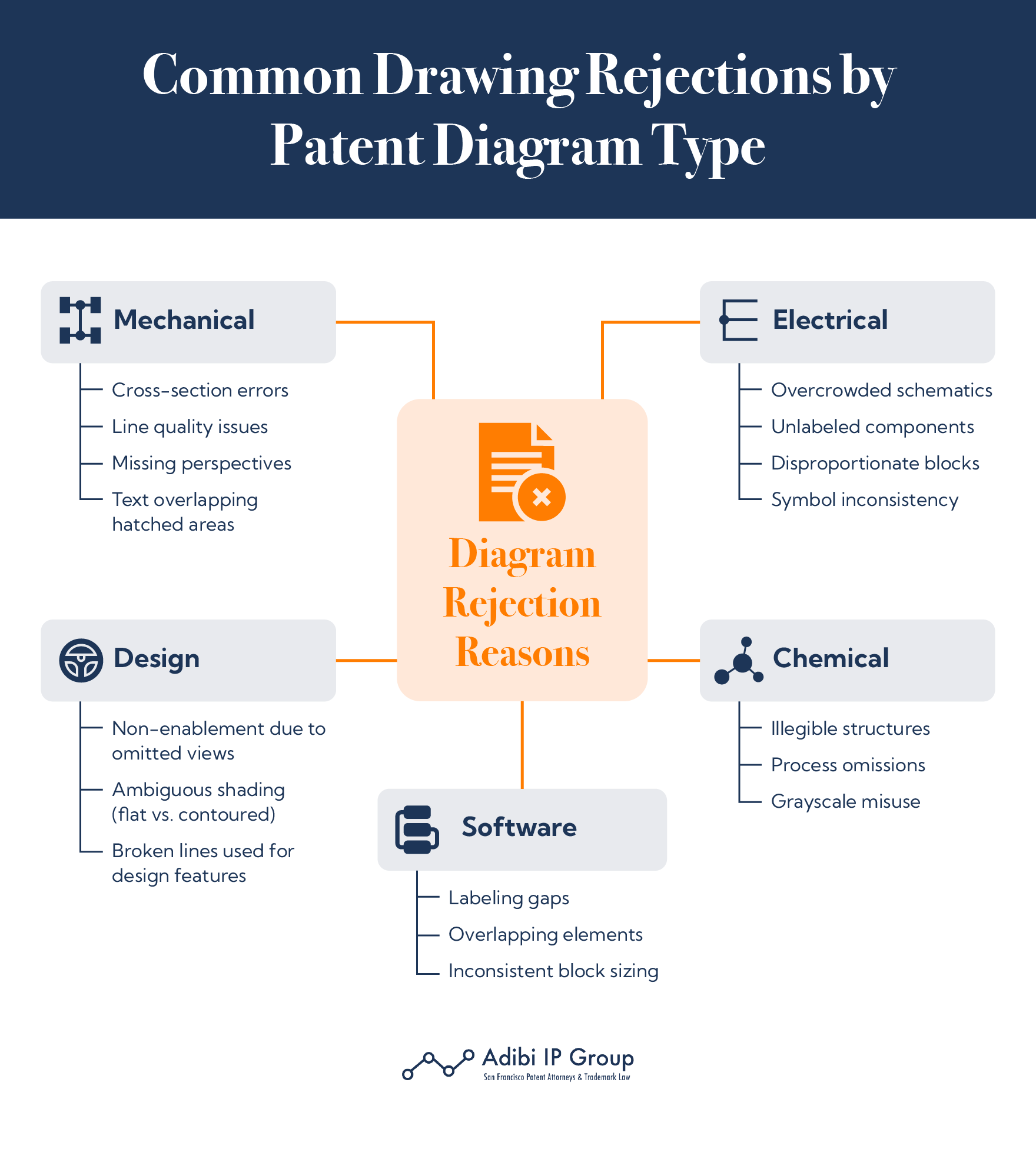
Examples of utility patent diagram types:
- Mechanical Patent Diagrams: Typically depict assemblies, exploded views, and sectional views to illustrate moving components and tolerances, using detailed line drawings to show fit and function.
- Electrical Patent Diagrams: Include circuit schematics, wiring diagrams, and PCB layouts, requiring standardized symbols and clear line weights.
- Chemical Patent Diagrams: Often use structural formulae, reaction schemes, and flow charts to represent molecular structures and processes, with flow sheets treated as drawings.
- Software Patent Diagrams: Encompass flowcharts, data flow diagrams, and user interface mockups, which must be clear, sequential, and annotated to convey algorithmic steps without ambiguity.
Applicability Across Patent Types
Whether you’re preparing a utility, plant, or design patent application, the same principle applies: your patent diagram must conform exactly to the statutory and regulatory requirements. Drawing rejections can occur in any patent type whenever illustrations don’t meet these technical specifications. Always consult the relevant MPEP chapters (General Patent Requirements: 600; Specialized Design Requirements: 1500; Specialized Plant Requirements: 1600) and 35 U.S.C. 113 to ensure compliance.
Common Mistakes Leading To Drawing Rejections
Examiners expect precision. When they encounter misaligned sectional cuts or vanishing points that don’t match, they question whether you understand your own design.
Ambiguities and Inconsistencies
Slight shifts in perspective between views, mismatched shading direction, or absent broken lines all scream “re-draw.” Maintain a single 45° upper-left light source for all figures to keep shadows uniform.
Surface transitions and contours should reflect depth and shape without confusion. Fuzzy indicators of dimension or inconsistent curves will raise flags. The drawings must give the examiner a complete and unified understanding of how the design actually looks.
Misrepresentations And Discrepancies
A drawing’s failure to represent the design truthfully can lead to enablement rejections under Section 112. This often happens when features appear distorted, disconnected, or disproportionate across views.
Leaving out a crucial side or failing to show how elements connect can prompt objections. The examiner must see how all design parts relate—any gap leaves them guessing.
Perspective views are particularly scrutinized. If foreshortening isn’t done correctly or vanishing points don’t line up, the drawing may seem manipulated. That impression alone can cause a rejection.
Navigating Specific Drawing Requirements
Most common drawing rejections trace back to a few common missteps with compliance or execution. Taking the time to meet formal drawing rules and properly prepare all views will eliminate many of these issues.
Compliance With PTO Requirements
A compliant design drawing begins with a proper foundation: white background, black ink (or its digital equivalent), and a layout visually supporting the claim. Claim elements must be in solid lines, while background or unclaimed context goes in broken lines.
Start with a white background, black ink (or equivalent PDF), and the six standard orthogonal views plus at least one perspective view. Follow EFS-Web PDF guidelines: embed images at least 300 dpi in TIFF, PNG, or GIF to avoid fuzzy lines.
Understanding Perspective Views And Shading
Multiple perspectives are necessary to capture all dimensions of a design. Most design applications include six orthogonal views—front, rear, top, bottom, left, and right—and at least one perspective view to tie it all together.
Shading defines shape. Use:
- Parallel lines for flat areas
- Gradient lines for curves
- Cross-hatching or texture lines for more detailed surfaces
Keep the light source consistent—it should come from the upper-left at a 45-degree angle. That baseline ensures shadows and highlights match from one figure to the next.
Strategies To Overcome Patent Diagram Rejections
Strong visuals and meticulous documentation go hand in hand with a smooth patent process. Solid strategy early on reduces revisions later and strengthens your case from the outset.
Effective Use Of Reference Characters And Labeling
Reference characters add clarity, but only if used with care. Numbers should remain consistent across all views and be placed cleanly outside design boundaries to avoid confusion.
Place reference numerals clearly outside design boundaries and keep them consistent across views. Label each figure (e.g., “Top View,” “Right Side View”) in 6 pt standard font beneath the drawing to orient the examiner quickly.
Handling Office Actions And Amendments
When you receive an Office action, mark up every sheet to highlight corrections. In your reply, explain how each change resolves the rejection and affirm that you haven’t introduced new matter. Consider an examiner interview to clarify issues—prepare an agenda, record the conversation, and file an Applicant Initiated Interview Request (PTOL-413A) as per USPTO guidelines.
Ensuring Success in Drawing Patent Applications
Thorough preparation and specialized support create a smoother, more effective path toward patent approval. Taking care at the start means fewer obstacles later.
Preparing For Resubmission And Revisions
Keep an organized record of every version of your patent drawings and all interactions with the USPTO. Maintain a checklist of common drawing rejections and run each submission through it before filing.
It helps to store patent diagram images at multiple angles and scales. If the examiner asks for more detail, you can respond quickly without recreating everything from scratch.
Always set internal review dates well before actual deadlines—ideally with a 2–3 week buffer. That time allows for unforeseen tweaks and keeps the application on track.
Leveraging Expert Guidance And Resources
Navigating the detailed drawing standards for patent diagrams demands a multi-faceted approach combining internal checklists, professional illustration, and the latest USPTO materials.
Patent illustrators familiar with CAD compliance and e-filing requirements can ensure your drawings meet the technical specs in 37 C.F.R. 1.84 and MPEP chapters. Their expertise in line weights, perspective views, and digital reproduction minimizes risks of reproducibility objections.
Let Adibi IP Group Assist You
When every line counts toward your claim, you need a partner who can help you align your patent diagram with examiner expectations, equip yourself with razor-sharp preventive checklists, and simplify prosecution with expert counsel.
Ready to transform your drawings from risky to rock-solid? Connect with Adibi IP Group’s patent specialists to refine every view and secure swift approval—schedule your free consultation today.